Garrattfan's Modelrailroading Pages
Fairlie Merddin Emrys
7.3 Detailing: cab driver's side
Detailing the cab is where the manual leaves you stranded. The text is limited to more or less the sequence in which the various appliances are mounted but it reveals almost nothing about the arrangement of the pipes, what purpose they serve and where they go to. The manual is clearly written by someone "in the know", ejector, injector, steam brake....what? The figures 140 to 156 provide some clues but leave a lot to be desired. Many a figure is not sharp, focus is often on the wrong parts and the chosen angles do not show everything you need to know. Thankfully the manual DVD comes with a lot of prototype images and they came to the rescue. It takes lot of puzzling, it took me a few hours of close observation of the figures and the images and making notes before the arrangement of the most important pipes became clear to me. But in the end I managed to piece it all together (I hope). An additional complication is the restricted space in the cab of the Fairlie, as in reality. The pipes run crisscross and in very tight spaces, so it needs a lot of thinking how and in which order the pipes must be made and placed. This page therefore contains a lot of photos to help you out, might you be building the loco yourself. |
|
Toolboxes |
|
Detailing the cab requires work on the pipe arrangement from the cab to the various appliances on the boiler. One such pipe, the ejector exhaust pipe (I will come to the function of it later), runs over the "deck" of the tank on the bottom end of the driver's side. There is a toolbox on this "deck" through which this pipe runs. To determine the correct location I needed to construct that toolbox first [276-279]. Being at it I also made the topside toolbox. This presented no special problems, only the top needed bending. |
|
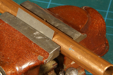 |
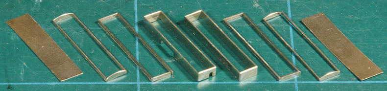
Bending the top of the toolbox was easy. A 12 mm copper water pipe suited the bill. Clamped in my vise, I slid the thin sheet in the available tapered gap. Do not clamp, this will distort the sheet, just push gently until it sticks. Then I bent it over the copper pipe with the aid of a flat piece of steel. Of course the sheet springs back but after doing so it had a perfect fit on the toolbox top. |
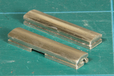 |
Two toolboxes, the font one goes on the bottom end and the ejector exhaust pipe runs through there.
With that done I could indicate the opening of the toolbox on the tank top. Only to discover that the hole in the short end of the toolbox is in the wrong place. Okay. I stored the toolboxes for now. |
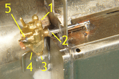
EjectorThe ejector [246-251] is a rather intricate large casting. It serves to create a vacuum for the brakes of the train and is powered by fresh steam from the manifold. The ejector needs five holes to drill: |
|
 |
|
Before completing the piping though I first added the injector casting. |
|
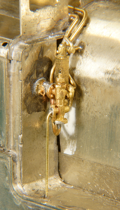
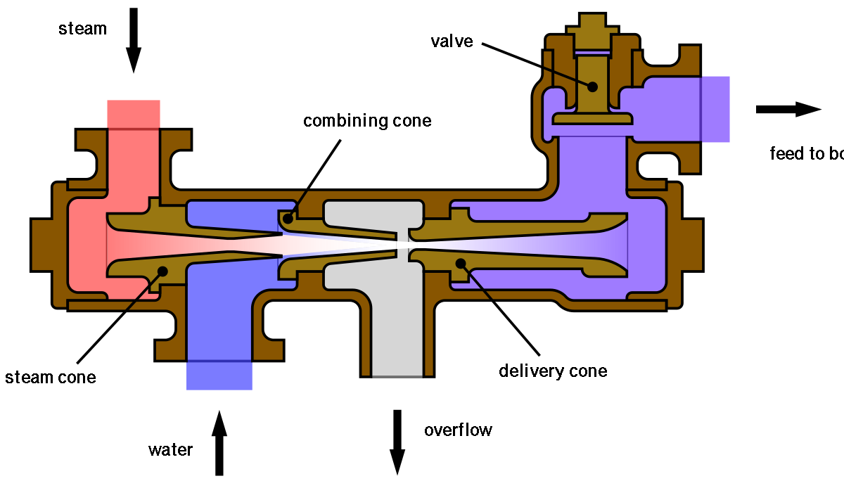
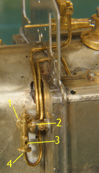
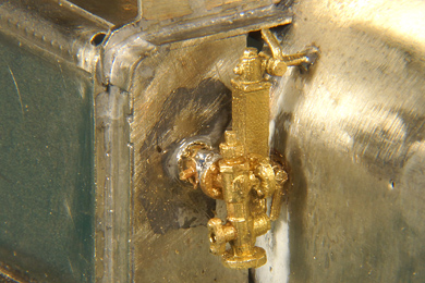
Injector [251]The injector injects (!) water in the boiler. A jet of fresh steam is injected in the body of the injector and creates a vacuum. This vacuum sucks water out of the tank and this water is sped up and carried away by the steamjet and pressed against the boiler pressure into the boiler. The injector has two advantages:
The setback is that it does not work very well when the body of the injector gets too hot, the hot water will simply evaporate, distroying the vacuum an thus blocking the proper working of the steam jet. |
From WikiPedia User Globbet licensed under the Creative Commons Attribution-Share Alike 3.0 |
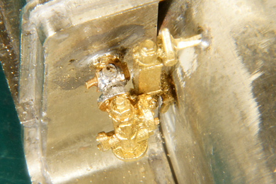
| For some reason the casting consists of two parts. First the base is soldered to the back of the tank with 240 C solder. Then the injector is soldered on that base with 180C solder. | |
The injector in place. |
The piping diagram of the injector alone |
The injector needs four holes
Pipes are bent in situ. Note that I removed the ejector for convenience. Stay as close to the rear of the tank as is humanly possible to avoid interference with the ejector. |
|
 |
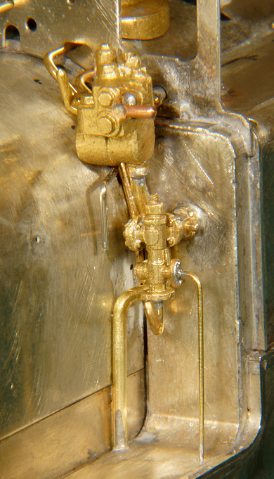
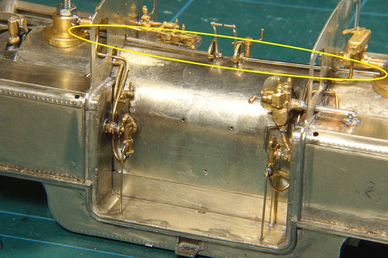
The fresh steam pipe runs all the way down from the manifold. The manifold takes fresh steam from the boiler and distributes it to various steam powered appliances. Note that I drilled completely through the connection point in the manifold. This way I could manipulate the pipe until the fit was good. When it is finally soldered and filed flush you won't be able to see it anymore. It is not soldered now because I need to drill a few more holes for other pipes so the manifold must be removed once more. |
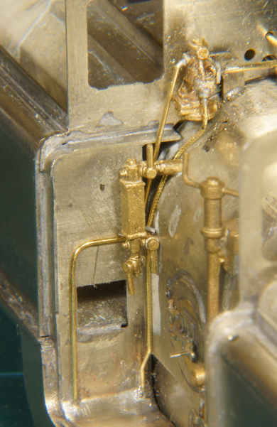
Ejector replaced and all pipes in place |
The spill pipe of the injector needs drilling a hole in the floor (0.5 mm) |
Water gauge [262] and second injector |
|
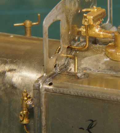
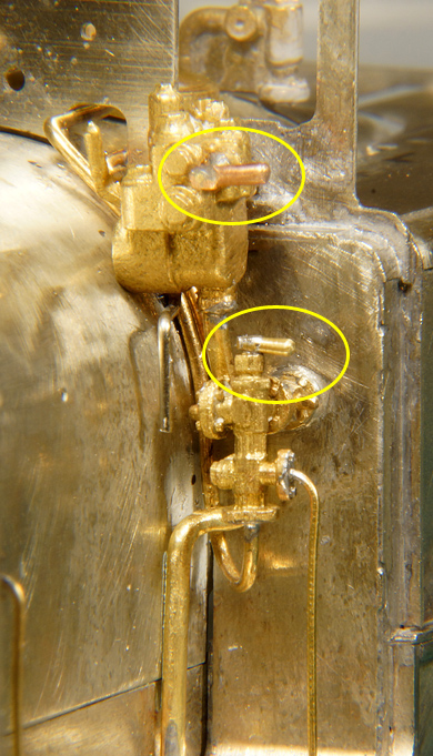
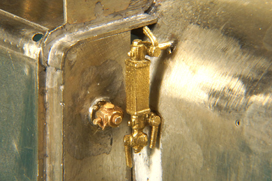
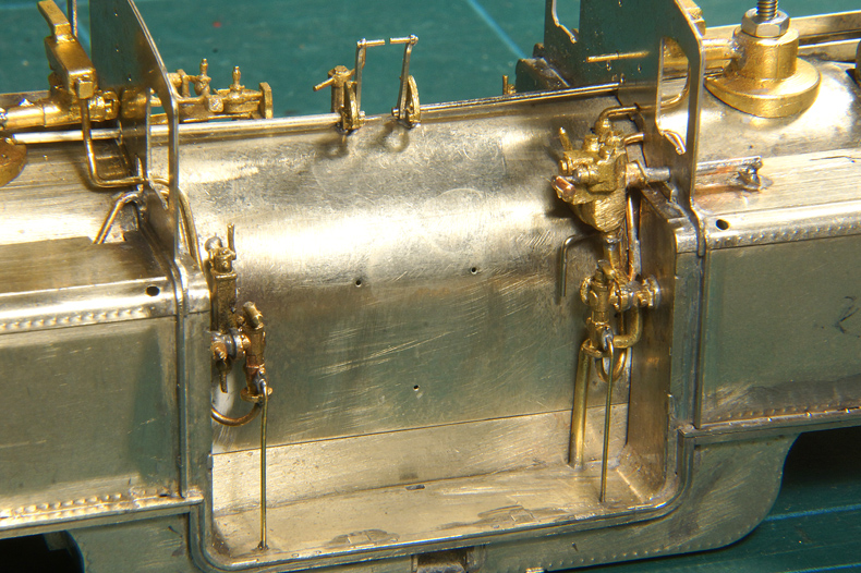
Water gauge at the top side. The injector's base is already soldered to the tank with 240 C solder. |
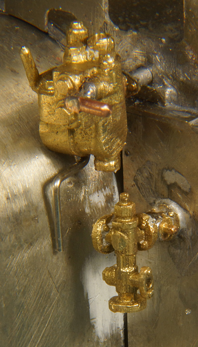
Second injector in place, soldered with 180 C solder. |
| For safety reasons every locomotive has two boiler filling appliances. This can be two injectors, two pumps or an injector and a pump. Merddin Emrys has two injectors, both the driver's side. | |
 |
The injector and the water gauge are too close together due to the placement of the etched holes. The two appliances interfere. I filed a bit in the casting of the injector to get a good fit. Images clearly show more clearance, but I was too lazy to change this arrangement. |
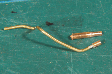 |
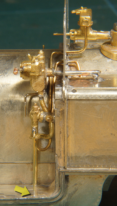
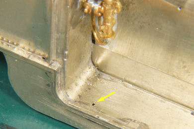
As a result I could not get all piping done in one go because the water gauge obstructed that. I had to split the fresh steam pipe to the injector in two pieces. I chose an obscure place for the separation. I made a connecting sleeve from a brass tube which I turned very thin, so I could slide the bottom end of the fresh steam pipe in. |
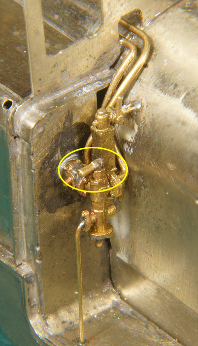
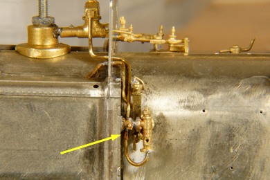 |
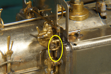
Like so. The arrow indicates the location of the connecting sleeve. Hardly visible. |
 |
Drilling a hole in the bottom for the drain pipe. For the first injector I soldered the spill pipe as a stub on the floor but after it dislodged twice during handling of the loco I decided I needed a more firm arrangement. So the second injector got this hole and I later corrected the first injector as well. |
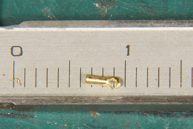 |
The injectors have an operating handle on top. This handle was not present on the casting and like the ejector I made one by turning a piece of brass rod. This one is even smaller than the ejector's handle. 2.5 mm handle length plus the mount, with a 0.8 mm hole in the mount. |
 |
 |
Regulator controls [256-261] |
|
The regulator controls are mounted on the top of the firebox. Not much to tell about except that getting both control levers lined out to perfection requires a bit of precise working.
|
|
Well, not bad for a weekend work? It is slow and time consuming work. You need 4 P's: Patience, Perseverance, Practise and Precision. |
|
Reverser control [263-264] |
|
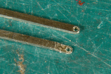 |
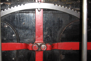
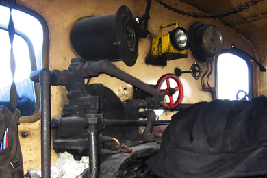
Photo from the manual DVD used with kind permission of Paul Martin ©2013 EDM Models |
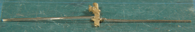
| The reverser lever and control bars are very simple things and need no explanation. Yet, I diverted from the manual in two ways. First I filed the rear side of the control bar at the hole end down to half the thickness, appr. 0.25 mm. Then I set a joggle in that end. The protoytpe has a fork but being so small I was happy with only a joggle to the fore. This had the added, but intentional advantage, that the control bar would lie flat on the firebox, like demonstrated below. | |
Left the original bar, right the filed and joggled version. |
|
Here we come to the second thing that I did a little different. The manual recommends using the heads of the brass pins to attach the lever and the control bars and file them flat. I considered them to be too big to my liking, so I simply used the normal pin method without the heads. Good enough. |
|
Steam brake [244, 252-255] |
|
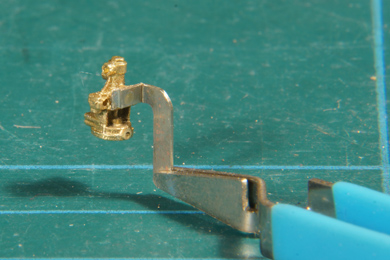
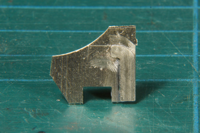
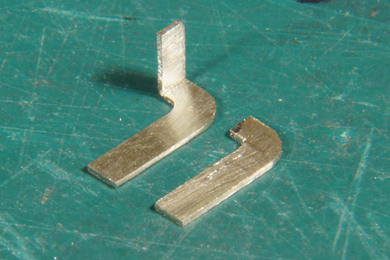
| The bracket on which the steam brake is to be mounted was a bit of a puzzle for me. I stared at it for some time and finally decided I needed an extra angle to it. This was duly mad from scrap nickel silver sheet. A 1.2 mm hole was drilled and the brake mounted with 240 C solder. | |
The original bracket soldered on a scrap piece of nickel silver with the extention already scribed. |
New and old bracket together. |
 |
|
 |
 |
Once the bracket cum brake was soldered into the appropriate slot on the firebox it turned out that I had drilled the hole for the operating bar, running over the firebox top from the driver's side, was a tad too far into the cab. The operating bar interfered with ejector on the driver's side. Luckily I could get to it with a drill in a hand chuck so I could drill a new hole without having to remove the brake.
|
|
 |
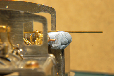 |
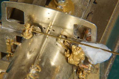
| Getting the operating bar in place proved to be a challenge as well. The logical thing to do was to solder the bracket on the driver's side and then fit the operating bar between the two brackets. But I just could not get it into place, hold it and solder it. So after some failed attempts I turned things around. I soldered the operating bar solid in the bracket on the fireman's side in the brake itself. To get it right I supported it with a bit of Blu Tack on the driver's side. This gave me ample opportunity the position the bar and later keep my hands free while soldering. | |
 |
|
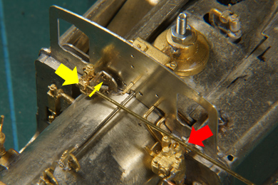
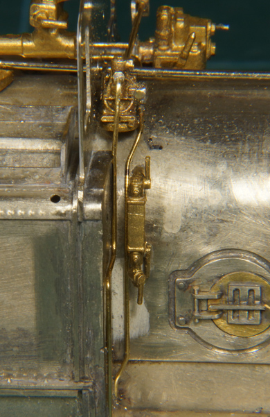
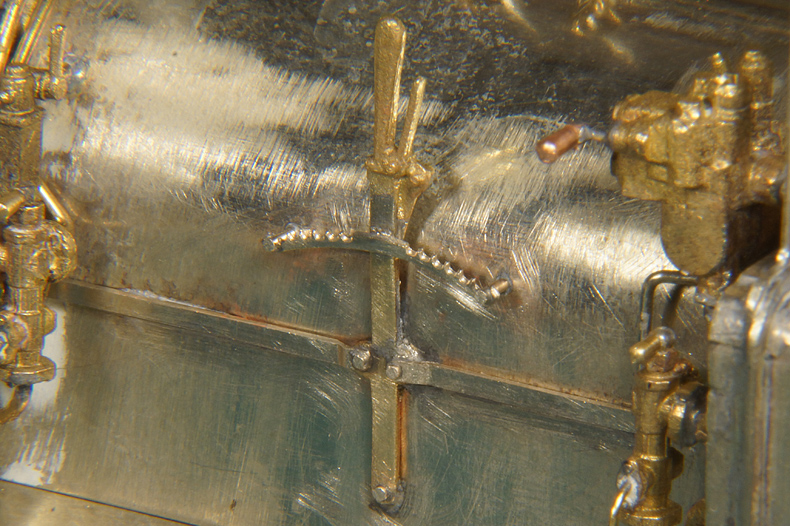
Then the operating bar provided me with a simple guide to position, hold and solder the other bracket. This lever was a surprise. It is not mentioned in the instructions. It hardly shows up in the prototype photographs. Yet there was a cast part of which I could initially not determine the position nor the function. A good deal of studying of photos before it dawned on me that it was a part of the brake system. The operating lever was then added to the bracket.
|
|
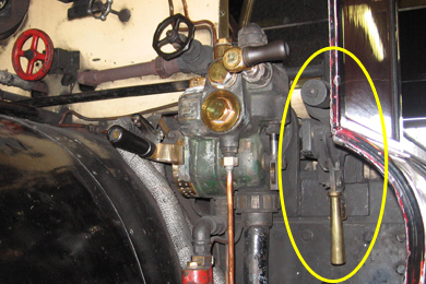
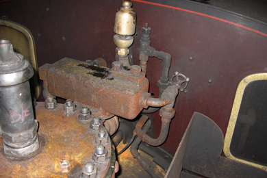
Photo from the manual DVD used with kind permission of Paul Martin ©2013 EDM Models |
Photo from the manual DVD used with kind permission of Paul Martin ©2013 EDM Models |
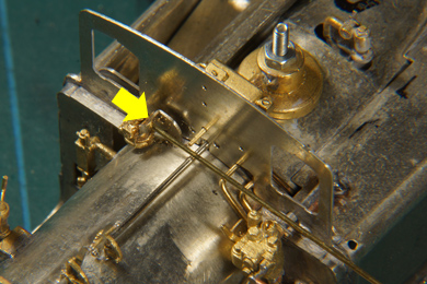
| The pipes leading to and from the steam brake also needed careful studying of photos. | |
 |
 |
| It is almost impossible mimick all pipes so I contended with a simpified representation. | |

Sign my
GuestBook